This chapter is adapted from Web Age course Solution Architect Training.
3.1 Shared Vision
Architecture is a team effort. All stakeholders must collaborate for success. A “shared vision” is a critical success factor. The “shared vision” must be understood & embraced by all stakeholders.
Grady Booch
An architecture is just a collective hunch, a shared hallucination, an assertion by a set of stakeholders about the nature of their observable world, be it a world that is or a world as they wish it to be. An architecture therefore serves as a means of anchoring an extended set of stakeholders to a common vision of that world, a vision around which they may rally, to which they are led, and for which they work collectively to make manifest. When I say that an architecture is a shared hallucination, I mean that an architecture-as-artifact is a naming of the mutually agreed-upon set of design decisions that shape a software-intensive system. While an architecture is just an abstraction of reality, an architecture-as-artifact is a declaration of that shared reality. In this way, that shared hallucination represents a common vision among a set of stakeholders as observed simultaneously through several different points of view and represented by a set of interlocking models.
Source:
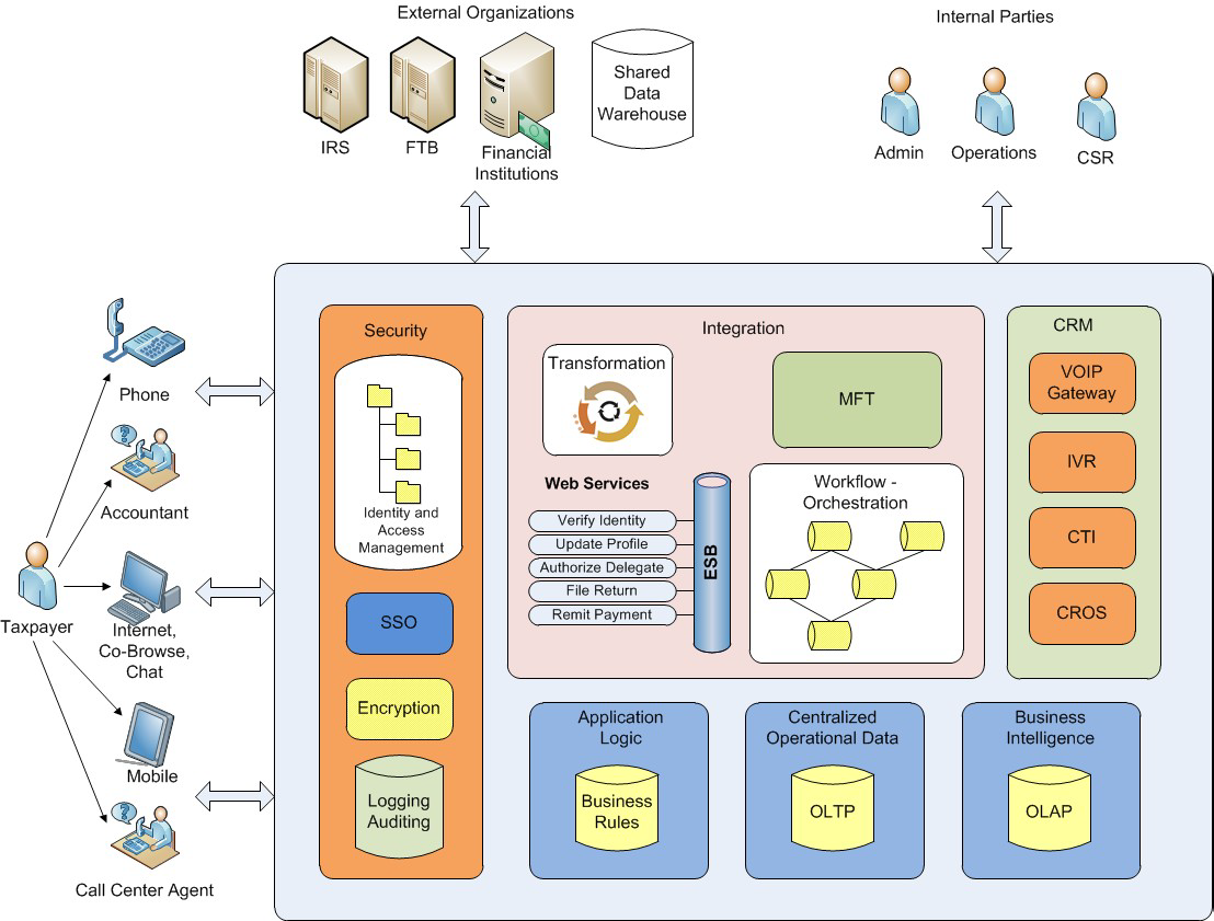
3.2 Example Shared Vision
3.3 Draw the Boundary
The first step in defining a software solution is to understand the boundaries of the solution. Without clear boundaries, a solution will be a moving target. Enables separating the components that reside internally within a solution and the components that reside externally. Boundaries are defined by understanding the overall intent of the solution, the external events that trigger the solution’s functionality and the external processes on which the solution has dependencies.
3.4 Well-defined Interface
“well defined interfaces” has been an architecture principle for many architecture styles throughout the past 30 years
Structured analysis and design
Message-based architecture
Object-oriented
Enterprise Application Integration (EAI)
Service-oriented architecture (SOA)
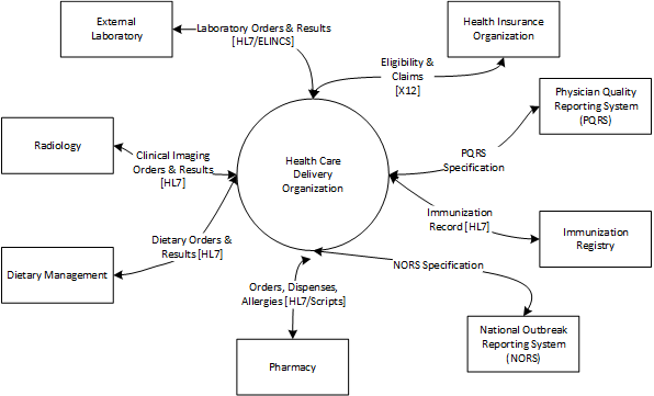
3.5 Example: Context Diagram
 Notes
Notes
• A fundamental activity for any architecture analysis is to define the system boundaries.
• After the system boundaries are identified, identifying your business partners and your system interfaces with them is the 2nd step.
• A Context diagram is a top-level Data Flow diagram that has just one Process element representing the system being modeled, showing its relationship to external systems.
• Understand industry standards to facilitate interoperability with partners.
3.6 Identify the External Interfaces
Interface specifications are critical to define interface frequency, protocols and expected volume. They must specify data elements: format as well as business meaning. They must specify acknowledgment & error handling mechanisms. They must be reviewed & approved by all impacted stakeholders.
3.7 Subsystems
A subsystem is a collection of classes, interfaces and components that make up a development package. It is defined such that they can be assigned to different development teams. It should have high cohesion and low coupling to ensure maintainability. Subsystems describe the design/buildtime system structure, interfaces and dependencies.
Subsystems
One of the most important functions of the architect and the architecture team is the careful partitioning of classes, interfaces and components into subsystems and the management of the dependencies between these subsystems. Subsystems can be farmed out to different development teams for detailed design and implementation. A good architecture will maximize cohesion within a subsystem and minimize the amount of coupling between the subsystems. This makes it much simpler for the development teams as they can spend less time communicating, negotiating and understanding the interfaces between the teams. The larger the project, the more important this becomes, especially if the teams are geographically dispersed. Subsystems are the level at which design, development, builds and testing are performed. Development teams should ensure that the build time directories and structures map to the subsystem structure defined in the architecture. If the development team finds it prudent to further divide a subsystem into finer-grained subsystems, the development team is responsible for the documentation for the fine-grained subsystems, not the
architecture team.
3.8 Subsystem Context Diagram
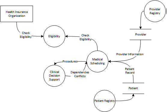 Subsystem diagrams illustrates system components that are designed, developed, and released independently.
3.9 Layers
The layers architectural pattern decomposes the functions of a software system into defined groups. Higher layers depend on lower layers. Advantages of layering are that it enhances portability, can skip builds of lower layers when they have not changed and it facilitate communication by suppressing detail.
Layers
Layers build on subsystems and provide additional organization. This leads to additional advantages such as improved portability, the ability to build higher level layers without the need to build lower levels that potentially change less frequently, and allows architects and designers to “rollup” subsystems of the architecture into very simple, high-level views, which make it easier to communicate system wide concepts. Higher level layers can depend on lower level layers but not vice versa. This keeps the architecture straightforward and helps to ensure that the rebuild of an upper layer does not require the rebuild of a lower layer. Formal or strict layering is a paradigm where any layer can depend only on the layer immediately below it. Relaxed layering allows a layer to depend on any layer below it. Layering is very common and has been proven to be a very successful technique.
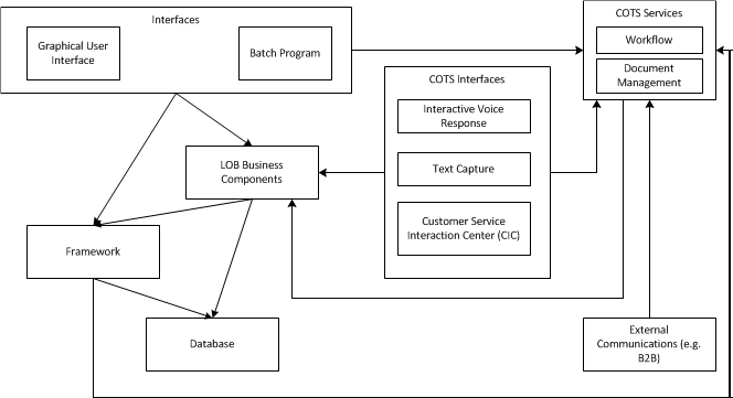
3.10 Example: Subsystems with Layers

Example: Subsystems with Layers
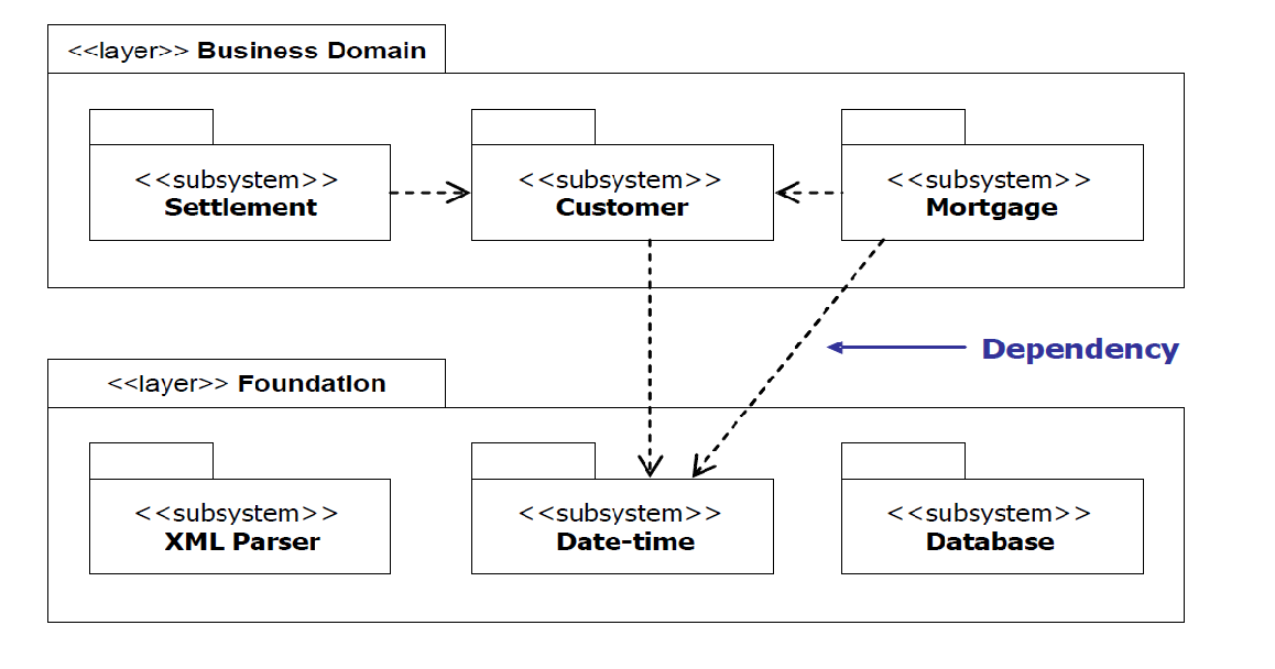
Subsystems and layers allow the system to be structured into smaller, more manageable, organized parts. Layers and subsystems are both represented using UML packages. The example above illustrates how a subsystem can depend on other subsystems in the same layer. It can also depend on subsystems in layers below it. You can imagine how convoluted the architecture would be if we allowed lower layers to depend on upper layers!
3.11 Components
A component is a modular and easily replaceable implementation construct. It provides services through a set of interfaces. It can be made up of several classes, interfaces and resources. It depends on a component framework to provide start-up and communication. It encapsulates both state and behavior. It describes the run-time system.
Components
Component-based development makes it easier to integrate off the shelf software, encourages reduced coupling and simplifies the process of replacing parts of the application without impacting the rest of the system. Components execute in a component framework which provides startup and communication services. There are several component models available including EJB, Java Beans, CORBA and COM. These models all require certain standard interfaces to be implemented so that the component is easily replaced by a more appropriate component (that implements the same interfaces) if the need arises. Components are often purchased rather than developed. They are started in a separate process or thread. They are configurable. Components are developed, tested and delivered separate from other components. They are found at run-time using location transparent naming services. Components can be very coarse-grained and made up of smaller components. Components can be of many different types such as databases, tables in databases, source files, jar files, EJBs, servlets, web browsers, Java applications, etc. This allows for high-level discussions about the major components of a system as well as detailed discussions regarding fine-grained components.
3.12 Decomposing the System
The architect is responsible for decomposing the system into subsystems, layers and components. The architectural style/pattern chosen typically specifies the allocation of responsibilities to components and their relationships (e.g. SOA, MVC). General architectural patterns provide guidance on general partitioning strategies .
3.13 Partitioning Patterns

Source:
Software Partitioning Strategies
There are many different ways to approach partitioning. The diagram illustrates some of the patterns related to partitioning. Each software architectural style (e.g. event driven architecture, SOA) has different strategies for partitioning a system.
3.14 Example Partitioning Based on Patterns
Model-View-Controller – the solution is composed of collection of model components, view components, and controller components.
SOA – the solution typically consists of business processes, sub-processes, composite services, and atomic services.
Master-Slave – the responsibilities are allocated between the controlling master component and slaves that handle each transaction.
Pipe & Filter – the responsibilities are allocated based on a sequential sequence of work where output from one process is input to the next process
3 Layer – the responsibilities are divided into 3 general categories: User interface, business logic, and data access. Each layer has multiple
components. The UI layer typically has components by UI object and event, the application/business logic is based on domain objects and methods and the data access layer is based on the data model.
3.15 Example: Healthcare SOA Framework
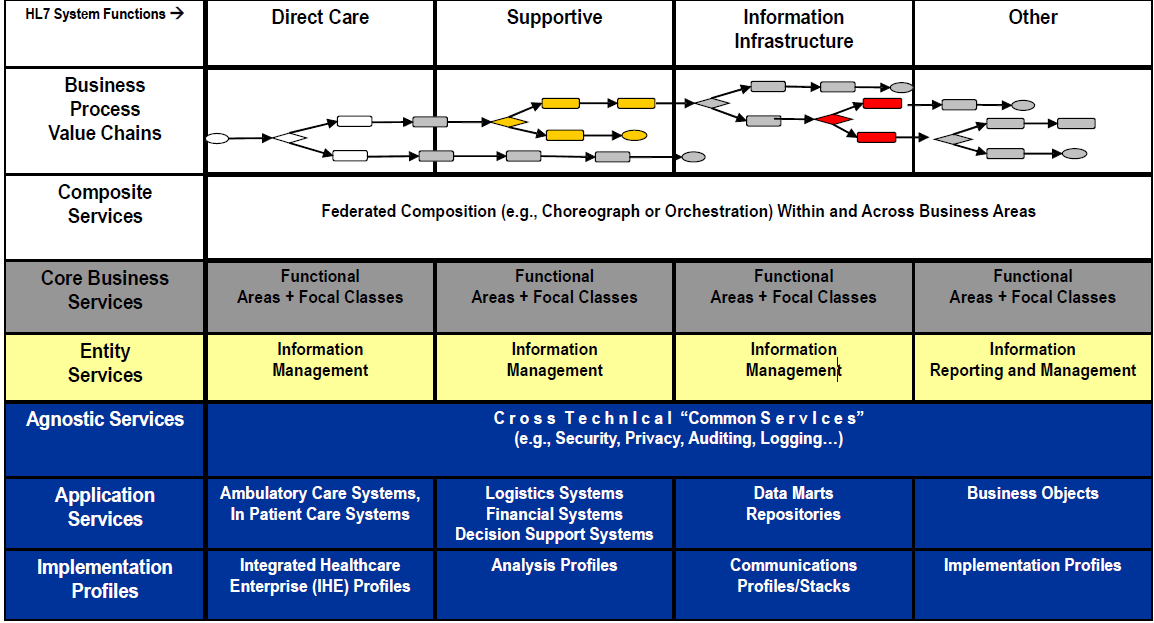
Example SOA Partitioning
The diagram illustrates the HL7 SOA Framework that shows the component types per architecture layer.
3.16 Requirements Allocation
Regardless of how the system is partitioned, the requirements must be allocated to the defined partitions (e.g. subsystems, layers, components). Requirements can be allocated to software components, hardware components, or manual procedures (i.e. non-automated tasks). Requirements may be associated with multiple components. Requirements may be split into multiple system requirements and then allocated to components, maintaining traceability to the original requirement. Requirements allocation ensures the component satisfies the requirements the component is “responsible for”.
3.17 Configuration Management Implications
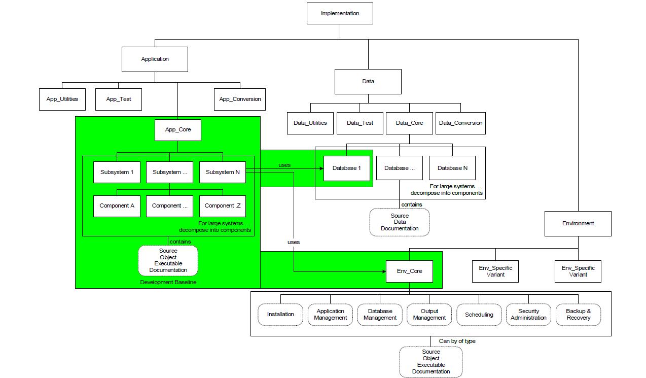
Notes
The design of the configuration management repository is based on the architecture partitioning. The build process is a bottom-process where the lowest level components are built first and then assembled to compose subsystems. The partitioning has an impact on the granularity of the software that can be released independently, the security (i.e. access control) placed on each subsystem and component items and the number and complexity of the interface and build dependencies.
3.18 Release Management Implications
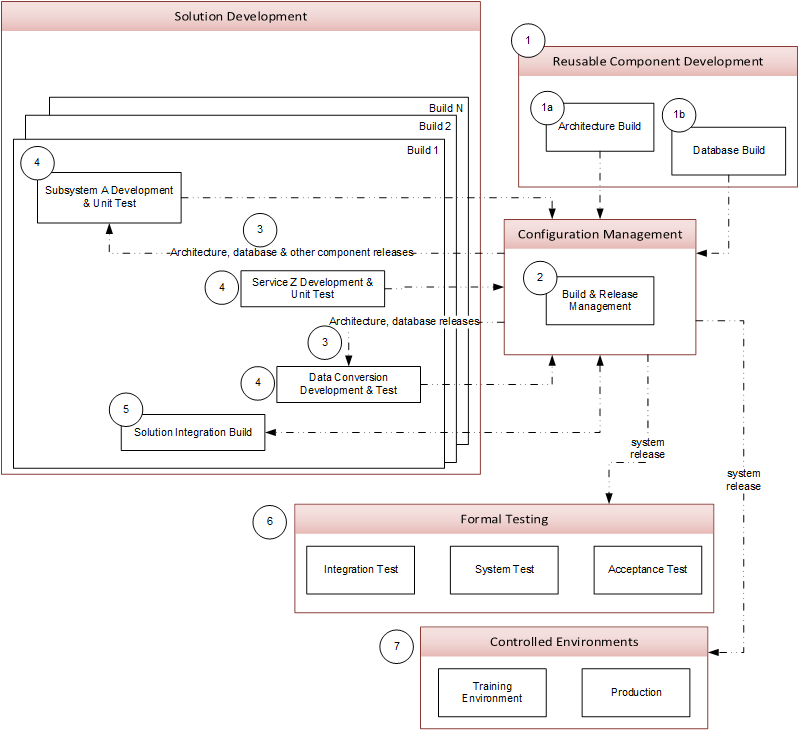
Release Management Considerations
The dependencies between the components must be considered when identifying the environments needed and the flow of software releases. The diagram illustrates a typical flow of releases considering a shared architecture and database schema.
3.19 Testing Implications
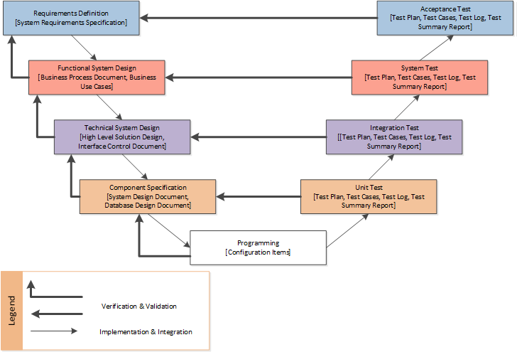 Test Strategy
The diagram illustrates a typical test strategy, where the test mirrors the bottom-up development process, where testing is performed at multiple levels.
3.20 Work Pattern & Skill Set Implications
Team Specialization
The diagram illustrates how teams are formed around the architecture and focus on specific component types.
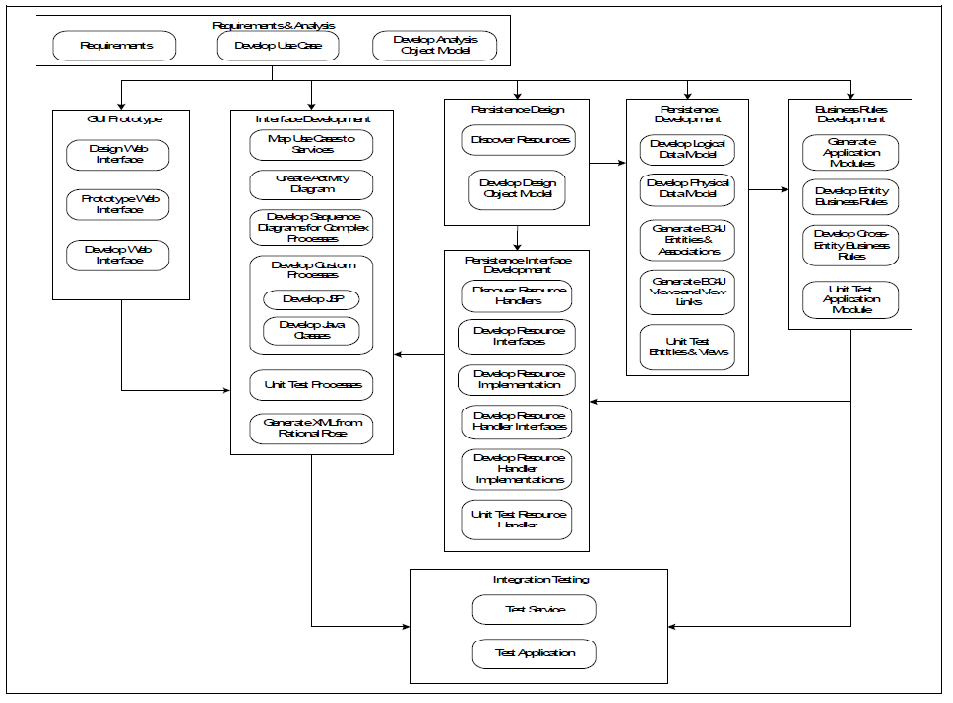
3.21 Work & Build Dependencies
Component Dependencies
The architect must understand the component dependencies and the impact on the development and build processes.
3.22 Increment/Sprint Planning
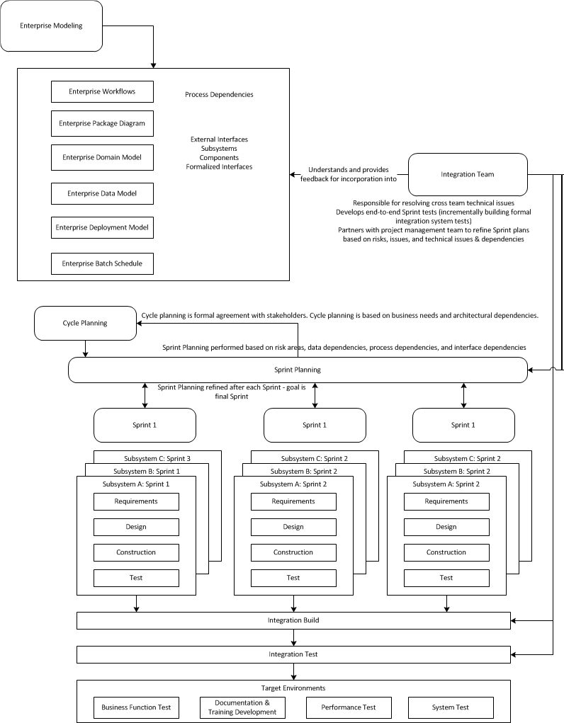
Increments & Sprints
In order to plan increments and sprints for large initiatives the architecture dependencies must be considered. Scaffolding or stubbing techniques can be used to facilitate incremental development.
3.23 Sizing Implications
 Estimating Development Costs
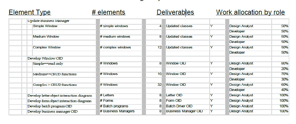
The architecture and partitioning strategy has an impact on how work is performed, by which role, and the number of development items needed.
The above example illustrates that estimating the work takes into account the number of development items by type, their complexity, and the role/skills required. Items types to consider are:
• User Interface items (e.g. windows)
• Component types based on pattern (e.g. business managers, controllers, views)
• Domain objects, with complexity based on # and complexity of business rules
• Database tables based on data model
• Letters and forms generated
• Reports
3.24 More Than Executable Architecture
So far we have focused on the architecture required to meet the functional requirements. There are two (2) other architectures to be considered. Development Architecture which is the processes, software, & hardware required to support the solution development, test, and deployment. Operations Architecture which is the processes, software & hardware required to support the monitoring & operations of the solution. Consider additional architectural components needed for testing (e.g. test data generation, test harnesses, load simulation), data conversion, and data quality verification.
3.25 Development Architecture
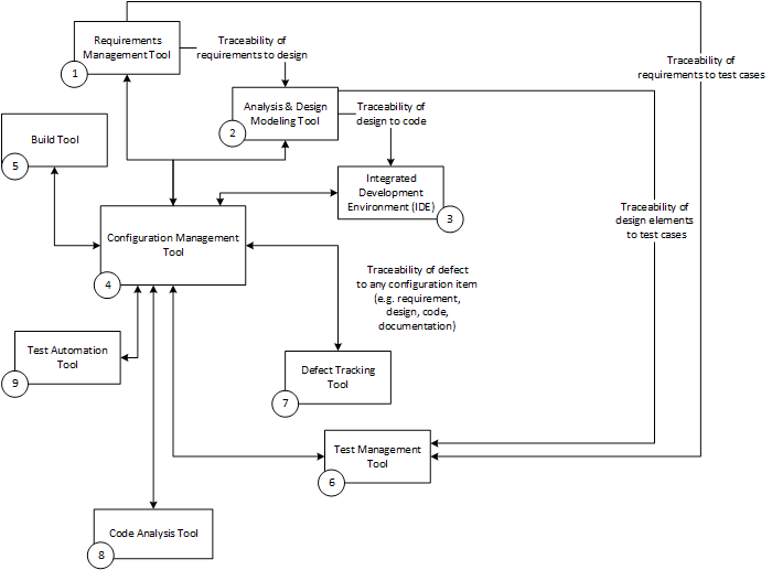 Development Environment Tool Integration
The more seamless the integration is between the development tools, the easier it is to perform new releases.
3.26 Operations Architecture
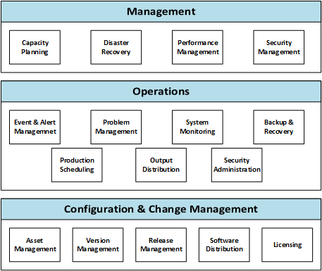
Operations Architecture Considerations
The solution must integrate with the Operations Architecture to meet key architecture qualities and requirements.
Examples:
• Performance can only be measured if the solution can be instrumented or an operations component is able to monitor the performance of the solution components.
• Supportability typically requires the solution’s ability to send alerts to a central Event & Alert Management component (e.g. management console/service) using a standard protocol (e.g. SNMP).
• Availability is achieved through automated backup and recovery capabilities.
• Centralized security administration is achieved through administration of an identify repository that the solution accesses using a standard protocol (e.g. LDAP).
• Coordinated, automated job execution is achieved through an enterprise job scheduling capability that executes solution jobs in a defined sequence based on established SLA time frames.
Establishing Solution Architecture Standards
A recommended method to ensure the operational quality attributes are considered (e.g. manageability, supportability), is to establish a standard set of requirements that all solutions must address. A sample of these requirements are provided. The solution shall support IETF Simple Network Management Protocol (SNMP) traps as a mechanism for event notification. The solution shall include a command line interface to allow automation of system processes (e.g. service startup, service shutdown). The solution should use access control information stored in an external LDAPv3 complaint directory. Security event logging will be enabled to provide a record of security related events that relate to major system security events, administrator functions, access to critical files, and user authentication activity. The solution must support fail-over to another instance or another server in the event of a failure. The solution must provide the ability to migrate setups/data between environments with minimal reconfigurations, reentry of data, or installs. The solution must support version control of the product’s development, test, or production configurations via an external management software product. The solution should provide end-to-end traceability of each transaction. Each message element of a transaction should be loggable each time it enters or leaves a host system of the solution.
3.27 Summary
In this tutorial, we explored core solution architecture methods, starting with the importance of establishing a Shared Vision. Next we discussed establishing the system boundaries. Then we looked at the principle of well-defined interfaces using subsystems, layers, and components. We discussed partitioning strategies and requirements allocation. We looked at the impact of architecture on configuration management, release management, and testing. Finally, reviewed development & operations architectures that should be considered.